 Resistive Load
I've built two 18watters. The first was built as a Tone Brewery PAM and it sounds great! The second is a conversion of an old Davis 106 PA amp but this one has a buzz problem. This page gives some of the details of what I've found.
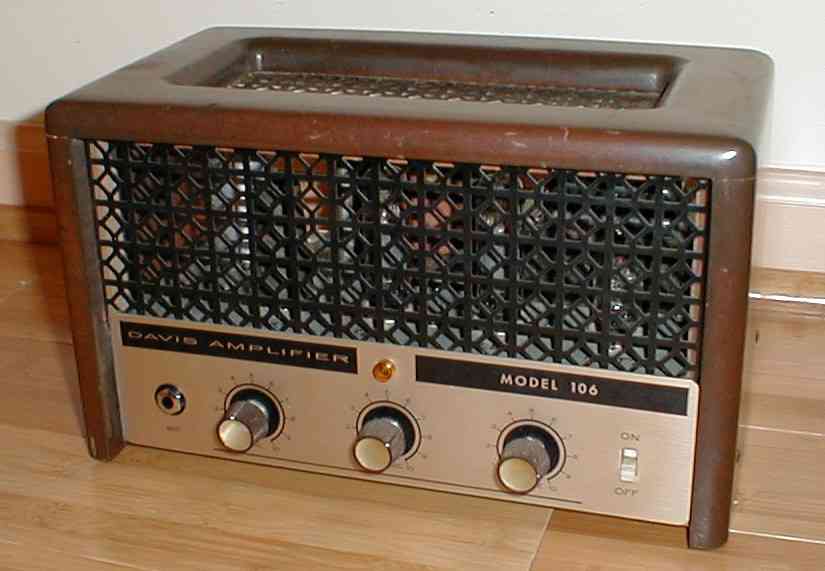
Here's a picture of the Davis amp...
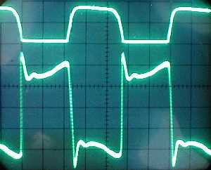
I dove into experimenting and scoping out the amp. First, I simply looked at the Davis without comparison to the PAM version. That didn't lead me to any conclusions and the next step was to compare the PAM to the Davis directly when driven by the same input signal. The following scope pictures come from driving both amps at the same time with a 200hz sine wave. Here's a comparison of the two amps ("good" PAM and "bad" Davis) driving a resistive load.
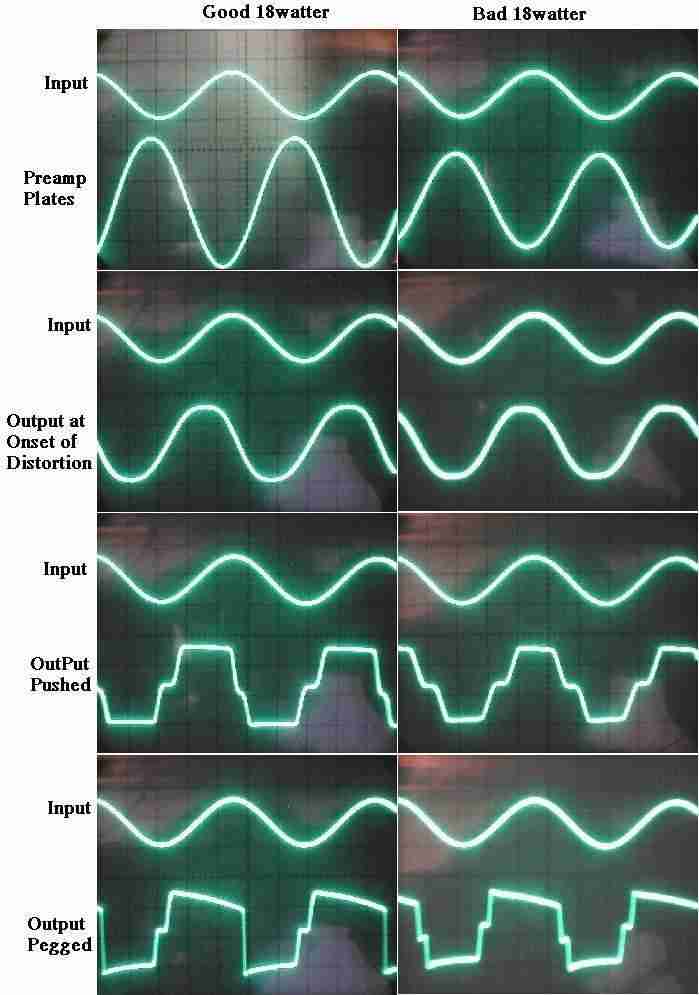
The top two graphs simply show that the preamp is doing it's job properly in both amps. The next graphs show the output at the onset of distortion, pushed and then pegged. When pushed, cross-over distortion appears in both, which I'll discuss in a bit. The only other significant difference is that the PAM's PI is not balanced (used 100K plate resistors on both PI plates) but I properly balanced the PI in the Davis in the course of trying to get rid of the buzz. As such, the Davis shows a nice, symmetrical wave shape, even when pegged. This is not considered part of the buzz problem as I started with the same unbalanced PI in the Davis when I first encountered the issue. However, the cross-over distortion is unsettling and I believe it contributes to harshness of the tone.
Driving a speaker alters the output wave shape considerably. The inductive load presented by the speaker causes impedance to rise for high frequencies. The result is overshoot at the points of high frequency content (kinks in the signal). Top curve is the "good" PAM and the bottom is the "bad" Davis.
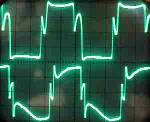
Cross-over distortion and the top & bottom clipping are where the overshoot happens. When pushed, the cross-over distortion becomes a drastic overshoot spike. Both the PAM and Davis exhibit this behavior but the PAM sounds good to me whlie the Davis has too much buzz. The only real difference between the two I can see in the output waveform is the shape at the clipping levels. Note how the PAM has little overshoot and recovery undershoot while the Davis has a substantial overshoot spike along with large undershoot on recovery. I've not be able to find the cause for this difference. I swapped OTs in the Davis without altering this behavior. I also used the same OT in the Davis and then the PAM and the problem remained in the Davis but does not show up in the PAM. So, it's not directly related to the OT. All other signals in the amp (EL84 grid, screens, cathode, PI plates, etc...) show no sign of this behavior in either the PAM or Davis. At present, I'm stumped by this.
I used excel to model the behavior of the PI and EL84, including grid clipping by the EL84 of the input signal. I also adjusted the level of blocking distortion (coupling cap charging from PI to EL84) to match the actual EL84 grid signals seen on the scope. Here's the actual grid signals measured.
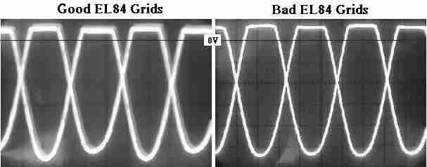
The key thing to notice is that the tops of the signals are clipped due to grid conduction. The bottom of
the signal is free to go far negative, despite the EL84 actually cutting off, making most of the signal
useless. Although difficult to really see on these graphs, the zero-crossing of the of the signal is not
at ground where it should be. It's ocurring near -17V (the scope is set for 10V/DIV and the clip
level ocurs at 7V). Ground level is at the solid division line just below the clipping. This proves there
is cap charging, shifting the grid signals to a DC value at about -17V.
Grid conduction at the EL84 when the input signal goes above 7V (the cathode voltage) charges the coupling
caps between the PI and EL84, shifting the signal down by 17V DC. That is the same as actually biasing the
EL84s to 17V Vkg, which is deep in cutoff.
The next step was to find out if this can cause cross-over distortion. The short answer is "YES!" I
built a simple model in excel to graph the results, allowing grid clipping to push the signals down.
With 15V offset caused by grid clipping, the above graph is the result. Each EL84's contribution to the
output is shown (arbitrary units centered at zero). Grid clipping causes each EL84 to deliver an
unbalanced duty cycle, spending more time in cutoff than saturation. This asymmetry allows for overlap
in time where both tubes are cutoff, which is the zero-output point, resulting in cross-over
distortion. The amp essentially biases itself to class B (actually beyond class B).
The "solution" for the cross-over distortion is pretty simple. We need only provide the analogous grid
clipping for the other end of the signal. That's easy with a zener diode in series with a regular diode
added to shunt the other side of the grid signal to the bias voltage (ground in the 18watter). Here's
a schematic.
And here's the resulting grid and output signals of the Davis amp after the installation. I only had 6.2V zeners for this experiment, so the signal is getting clipped a bit too much. The conclusion is still the same. This method will get rid of the cross-over distortion produced. The trick is to chose a zener value to clip the grid signal somewhere beyond the tube cutoff grid voltage. By providing the symetrical clipping, the coupling caps are provided the needed discharge path to avoid the problem. I purposely chose a clipping level that is beyond the EL84's cutoff voltage. As such, this clipping is not part of the output signal. The EL84 is still responsible for true output signal clipping because it is cutting off before the input signal is clipped. The zeners are simply eliminating coupling cap charging by counter balancing the grid conduction.
This is it!!!!! I just plugged in the amp to hear it. ALL the odd sounds I was hearing are gone! Woo-hoo!!!
This is the ticket to smoothing out the sound!!!!
More experiments are coming.... I added the same circuit to the PAM and it has no effect on sound, despite
visibly getting rid of cross-over distortion. How can this be??? The PAM is magic. :)
An alternative solution could be cathode or FET followers after the PI coupling caps to isolate them from the
EL84. This would achieve the same thing and, as Glenn J pointed out on the BBS, this has the advantange of
slightly boosting output power because the follower can drive the grid further into conduction thus providing
higher tube saturation current. The net signal shape will be virtually identical to that of the zener solution.
The down side of the follower is more difficult implementation needing a negative voltage supply on the pull
down side. This would be easier, in a fixed-bias amp where negative voltage is already available.
Kursad mentioned that the "duty cycle modulation" caused by the coupling cap charging might be desireable
to some degree. This is certainly a valid point I hadn't considered. Being an engineer, my instinct is to
get rid of distortion and I forget that all the subtle, unplanned, mostly accidental stuff going on in a
tube amp is exactly what we want. My reaction to the cross-over distortion was to kill it without ever
thinking that might be part of "good" overdrive sound. Anyway, you can experiment with the zener value to
allow some amount of cap charging. Try values from ~8V up to ~20V. What's there to lose?!
Go To BBS Discussion of This Topic
